Digital I/O
pinMode(pin[, mode])
-
pin<number|number[]>The pin number (or array of pin numbers) which can support GPIO function. -
mode<number>The pin modeINPUT (0)orOUTPUT (1)orINPUT_PULLUP (2)** orINPUT_PULLDOWN (3).**. Default:
INPUT
Set the mode of the GPIO pin to INPUT , OUTPUT, INPUT_PULLUP, or INPUT_PULLDOWN. A RangeError will be thrown if pin does not support GPIO function. Use INPUT_PULLUPwhen you want to enable internal pull-up for this pin and use INPUT_PULLDOWN when you want to enable internal pull-down.
// Set pin 1 to output mode.
pinMode(1, OUTPUT); // Set the pin 1 to output mode.
digitalWrite(1, HIGH); // Set the pin 1 to HIGH.
You can set mode for multiple GPIO pins at once by passing an array of pin numbers.
pinMode([0, 1, 2, 3], OUTPUT);

// equivalent to
pinMode(0, OUTPUT);
pinMode(1, OUTPUT);
pinMode(2, OUTPUT);
pinMode(3, OUTPUT);
digitalRead(pin)
pin<number>The pin number which can support GPIO function.- Returns:
<number>The return value isHIGH (1)orLOW (0)
Read the digital input from the GPIO INPUT pin. A RangeError will be thrown if pin does not support GPIO function.
// Read digital value from the pin 1.
pinMode(1, INPUT); // Set the pin 1 to input mode
var value = digitalRead(1); // Read the value from the pin 1.
digitalWrite(pin[, value])
pin<number|number[]>The pin number (or array of pin numbers) which can support GPIO function.value<number>The value could beHIGH (1)orLOW (0). If an array of pin numbers are given a number (greater than 1) can be used. Default:LOW
Set the GPIO OUTPUT pin to HIGH or LOW. A RangeError will be thrown if pin does not support GPIO function.
// Set the pin 1 to HIGH.
pinMode(1, OUTPUT); // Set the pin 1 to output mode
digitalWrite(1, HIGH); // Set the pin 1 to HIGH
You can set multiple GPIO pins at once by passing an array of pin numbers. The last element in the array corresponds to the last significant bit (LSB) of the value.
var pins = [0, 1, 2, 3, 4, 5, 6, 7];
digitalWrite(pins, 0b11001010);

// equivalent to
digitalWrite(0, HIGH);
digitalWrite(1, HIGH);
digitalWrite(2, LOW);
digitalWrite(3, LOW);
digitalWrite(4, HIGH);
digitalWrite(5, LOW);
digitalWrite(6, HIGH);
digitalWrite(7, LOW);
digitalToggle(pin)
pin<number>The pin number which can support GPIO function.
Set the GPIO OUTPUT pin to the reverse state of the current state. Set to HIGH if the current state is LOW. Set to LOW if the current state is HIGH. A RangeError will be thrown if pin does not support GPIO function.
// Set the pin 1 to HIGH and toggle (Set to LOW)
pinMode(1, OUTPUT); // Set the pin 1 to GPIO OUTPUT
digitalWrite(1, HIGH); // Set the pin 1 to HIGH
digitalToggle(1); // Toggle the pin 1, change the pin state to LOW from HIGH.
setWatch(callback, pin[, events[, debounce]])
callback<function>The function is called when theeventis triggered on thepin.pin<number>The pin number is passed as the first argument to the callback.
pin<number>The pin number which can support GPIO function.events<number>set the events of thepin. There are five events,LOW_LEVEL (1),HIGH_LEVEL (2)FALLING (4),RISING (8), andCHANGE (12). Default:CHANGE.debounce<number>debounce time in ms (milliseconds). Default:0ms- Returns:
<number>the ID of the watcher.
Run the callback function when the events is triggered on the pin. There are five events. The FALLING event is triggered when the pin state is changed from HIGH to LOW. The LOW_LEVEL (1)event is triggered when the pin is LOW state and The HIGH_LEVEL (2) event is triggered when the pin is HIGH state. The RISING (1) event is triggered when the pin state is changed from LOW to HIGH. The CHANGE event is triggered when the pin state is changed to any states, which means the CHANGE event is the same as the FALLING + RISING events. The debounce time can be set when you can see the bouncing on the GPIO pin. A RangeError will be thrown if pin does not support GPIO function.
Before calling this function, you have to set the pin mode as INPUT , INPUT_PULLUP or INPUT_PULLDOWN.
// Print out 'click' string to the terminal when user press the button.
var pin = 0; // Pin to watch
pinMode(pin, INPUT_PULLDOWN); // Set the pin mode to INPUT_PULLDOWN.
var id = setWatch(
  function () {
    console.log('click'); // Print out the 'click' to the terminal.
  },
  pin,
  RISING,
  10
); // Set falling event with 10ms debouncing time.
clearWatch(id)
id<number>The ID of the watcher which is the return value of thesetWatch()function.
Stop watching the event which is set by setWatch() function.
// Print out 'click' string to the terminal when user press the button.
var pin = 0; // Pin to watch
pinMode(pin, INPUT_PULLDOWN); // Set the pin mode to INPUT_PULLDOWN.
var id = setWatch(
  function () {
    console.log('click'); // Print out the 'click' to the terminal.
  },
  pin,
  RISING,
  10
); // Set falling event with 10ms debouncing time.
clearWatch(id); // Stop watching the on-board pin event.
pulseRead(pin, count[, options])
pin<number>The pin number which can support GPIO function.count<number>The number of pulse to read.options<object>timeout<number>timeout in us(microseconds). Default:1000000startState<number>Start to read the pulse from this state. Default:undefinedmode<number>Pin mode to read pulse.trigger<object>pin<number>Pin number to trigger. Default: same withpinstartState<number>Start state for trigger. Default:LOWinterval<number[]>Pulse timing in microseconds. Refer topulseWrite.
- Returns:
<number[]>Array of the pulse timing. It returnsnullif the pin state is not changed untiltimeout
Read the pin state change timing from startState. It returns the microseconds state changing timing if the state is changed count times or for timeout microseconds.
// Read 10 pulse timing on the pin 0
pinMode(0, INPUT);
var pulse = pulseRead(0, 10);
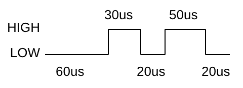
console.log(pulse);If startState is HIGH (1) the system wait until the pin state to HIGH and start to measure pulse timing. The If startState isundefined, the system start to measure pulse timing immediately and user can't know which pulse timing is HIGH or LOW. Assume that the pulses are given as below timing diagram, you can get [30, 20, 50] with the below example code.
// Read 10 pulse timing with 50ms timeout.
pinMode(0, INPUT);
// Wait until HIGH state detection
var pulse = pulseRead(0, 3, { timeout: 50000, startState: HIGH });
console.log(pulse); // [30, 20, 50]
If trigger options is given, it generates trigger pulse just before to read pulse. The fields of trigger object is corresponds to the parameter of pulseWrite(). It is useful to avoid the delay time between triggering and pulse reading.
// 10us trigger pulse before reading
var pulse = pulseRead(0, 10, {
  mode: INPUT,
  trigger: {
    pin: 1,
    startState: LOW,
    interval: [2, 10];
  }
});
console.log(pulse);
You should be consider the CPU process time in the very first output array data. This means that the very first timing data is less than your expected timing due to CPU process time.
pulseWrite(pin, startState, interval)
pin<number>The pin number which can support GPIO function.startState<number>Start state.interval<number[]>Pulse timing in microseconds.- Returns:
<number>Length of the written pulse, it's the same as the length of theintervalarray.
Generates the digital pulse on the pin with microseconds timing. The state change timing from startState. It returns the number of the written pulse.
// Generates pulse on the pin 0
pinMode(0, OUTPUT);
pulseWrite(0, LOW, [60, 30, 20, 50, 20]);